FPV Camera Drone
currentA quadcopter I designed, budgeted, printed, soldered, assembled, programmed, and flew.
- CAD
- 3D Printing
- PID
- FPV
- Embedded
- Onshape
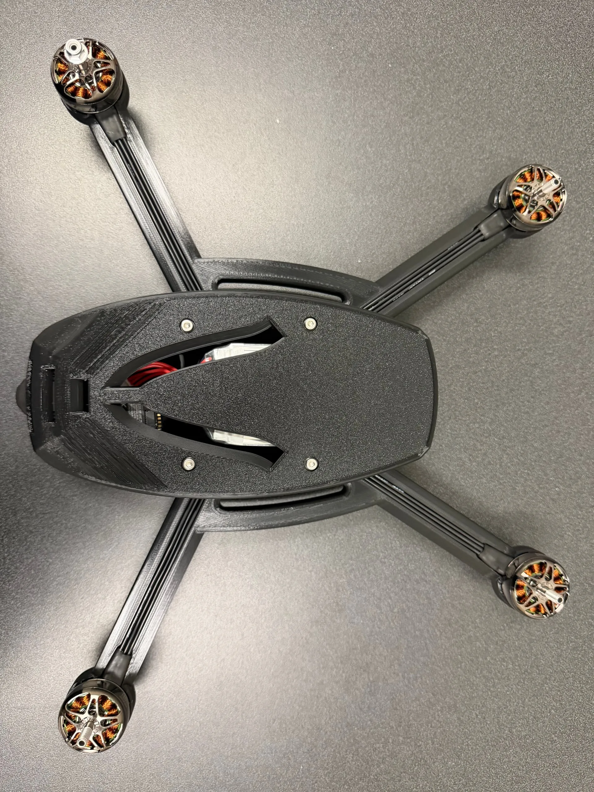
Back in high school, one of my teammates and mentors brought his personal drone out to film our games. I wanted one of my own, but buying a fully-assembled drone off the market is expensive, non-customizable, and always misses some crucial feature. As an engineer specializing in robotics and embedded AI, there was only one feasible solution. So I built my own, iterating on what I’d already built (and broken) on a previous attempt.
Three full iterations over two years, each a rebuild rather than a patch. Starting with hand sketches → full Onshape CAD → a 3D-printed frame I designed myself → each wire and board soldered by hand → a fully assembled quadcopter.
fpv-drone-v3.glb · Onshape assembly
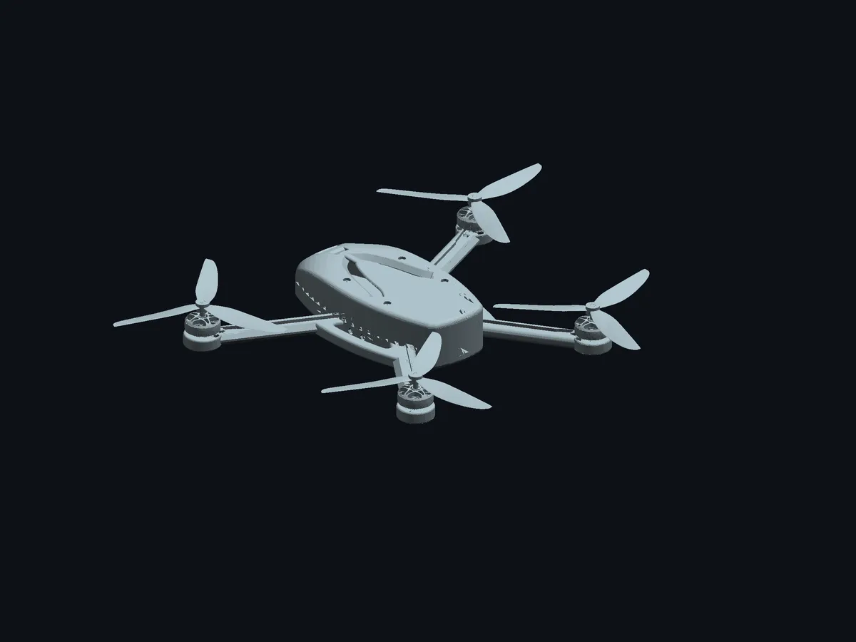
Drag to orbit, scroll to zoom. The window buttons work too.
Above is the actual v3 CAD assembly: the real model, not a mockup. Drag to orbit it, and hit the props toggle to spin them up.
A word on ground effect
Anyone who’s ever designed an aircraft probably knows of this little concept called the ground effect. And my team learned this the hard way back in our v1 testing. When any aircraft (helicopter, drone, rocket, even an airplane) takes off, it makes lift by throwing air downward fast (Newton’s third law: push air down, it pushes you back up). Close to the ground, a lot of that air bounces back off the surface and shoves the aircraft up again, so near the ground you get almost double the lift. While this seems great at first, there is an unfortunate catch: that reflected air scatters in every direction, throwing the aircraft unpredictably off course. It’s why drones take off instantly instead of easing up: the longer you sit in the ground effect, the more likely it flings you sideways into a crash.
v1: the one that couldn’t beat the ground
v1 was my senior-year project for Advanced Software Engineering II, the highest computer science course my high school offered. In this course, the class splits into teams of three or four and each group takes one big project start to finish over a semester. We set out to build a drone.
Most of our fight was with constraints, not physics. The school required constant safety measures: ground tethers, extra structure to shield the propellers, constant faculty supervision. All that bulk pushed the weight past the maximum load our motors could lift. It never really took off. Riding the near-2x lift from ground effect it could rise a few millimeters and be nudged around, but would never climb higher than the ground effect would push it. A semester of testing constrained by faculty schedules didn’t provide enough time to fix that.
The bill of materials tells the story: an Arduino ESP32 Nano, MPU6050 IMU, breadboards and jumper wires, 4 standalone ESCs rather than a 4-in-1 stack, and a $250 budget. It was a first attempt, and it taught me exactly what I needed to know for the next build to fly.
v2: proving it could get airborne
v2 had one job: beat the ground effect and get into the air. Real flight control could come later. I cut the weight to about a third of v1, roughly tripled the budget to ~$750, and added proper flight control software and hardware.
It worked: v2 got off the ground, and I even had a bit of control in the air. Everything I needed from it, plus a little more.
Specs: T-Motor Velox F7 SE flight-controller / 4-in-1-ESC stack · 2306 v2 1500KV motors · 6S 2600mAh LiPo · DJI O4 Pro camera.
v3: the one that flies
v3 targeted turning “airborne” into “flyable,” and building something that could survive the elements. Re-engineered against the specific failures of the first two:
| Change | Why |
|---|---|
| Airfoiled arms | Reduce drag through the frame instead of treating the airframe as dead weight |
| Rainproof enclosures | It is used outdoors, at fields, in the Pacific Northwest and in London |
| Working battery cooling | Thermal headroom is what turns a short flight into a long one |
| 100 g lighter | Every gram is thrust budget and flight time |
| Stronger motors | Authority to actually execute a commanded correction |
| Bluetooth PID tuning | Retune gains at the field without tethering to a laptop |
That last one changed how fast I could iterate more than anything else on the list. Tuning a PID loop is empirical: you fly, watch the oscillation, adjust. Doing that over a USB cable means a full landing and teardown per attempt; 10 minutes to tune one number. Doing it over Bluetooth means adjusting between throws; 10 seconds compared to 10 minutes.
Result: stable, controlled flight. v3 responds to all controls on the sticks rather than just staying airborne, with roughly 30-minute endurance. The frame and firmware are also built for autonomous features like automatic sideline return on low battery; I haven’t implemented that yet, but it’s the plan once I’m playing in college.
Specs: SpeedyBee F7 V3 (Bluetooth) flight-controller / 4-in-1-ESC stack · 2807 1300KV motors · 6S 2600mAh LiPo · DJI O4 Pro camera.
The frames
I designed and 3D-printed every frame; below, you can see the engineering grow and evolve across the three. v1 was held together with zip ties, hot glue, and prayers. v2 had proper mounting holes but still leaned on zip ties for the battery and for extra strength on the arms. v3 has comprehensive mounting holes with threaded inserts, so the whole thing bolts together and comes apart cleanly. Modular by design, ready for whatever I add next. It’s also the most aerodynamic of the three: airfoiled arms and chamfered battery-cooling vents, shaped to cut drag instead of just carrying parts.
Footage
media/drone/
Why this project
The work I’ve completed on this drone has melded together all of what I do: CAD and fabrication, embedded control, a bit of computer vision, and the sport I love most. It was also an open-ended design project for me to prove my own capabilities to myself; I provided the challenge to myself, and every constraint after that was mine to find and overcome.